xPlora: Safe Box
Introduction
We all have special things we want to keep safe, like some saved-up money, a tiny note from a friend, a favorite piece of jewelry, or a lucky stone.
These little treasures deserve a special place where they can stay private and protected.
That’s where a safe box comes in. A safe box gives you your own space to store your treasures and keep them safe from curious eyes or sneaky hands.
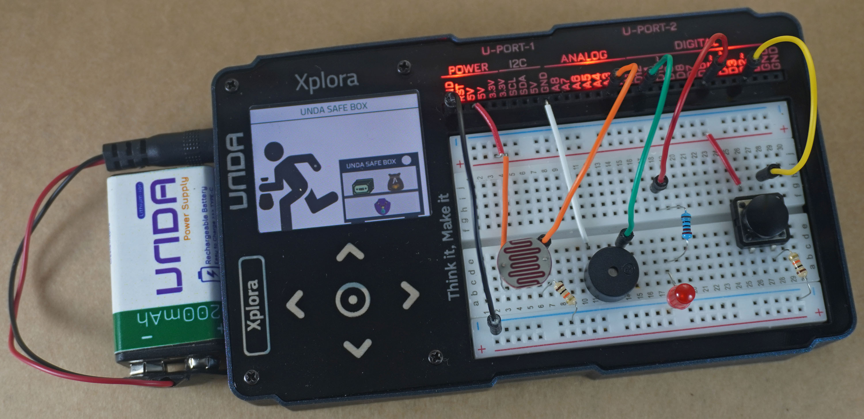
In this project, we’ll build our very own safe box, the UNDA Safe Box.
This Safe Box doesn’t just hold your treasures, it can tell when someone is getting too close.
It uses a light sensor that knows when someone comes near the box and blocks the light. The sensor tells the buzzer, which makes a loud sound, and an LED that flashes. This lets the owner know that someone is too close to their treasures and also gives the peeker a scare.
This is a fun project to let you know when someone is being a little too nosy, whether it's a friend or a sibling. Let’s get building and make your very own UNDA Safe Box.
Build the project
In this section we will explore how to use UNDA Xplora to build a Safe Box.
Components
To build the project you will need:
| Component | Description |
|---|---|
| 1 x Light Sensor (LDR) | 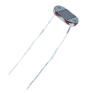 |
| 1 x Buzzer | 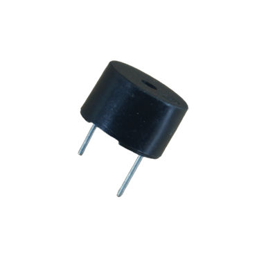 |
| 1 x pushbutton | 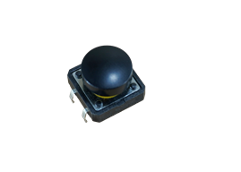 |
| 1 x Red LED | 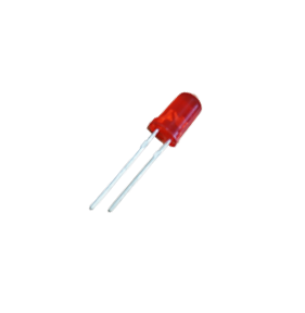 |
| 1 x resistor (220 Ohm) | 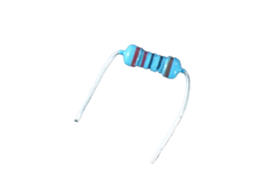 |
| 2 x resistor (10Kilo-Ohm) | 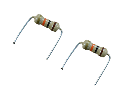 |
| 5 x jumper wire | 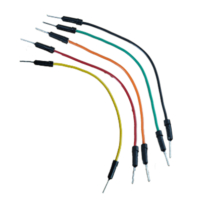 |
| 4 x breadboarding jumper wire | 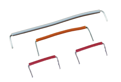 |
| 1 x battery connector | 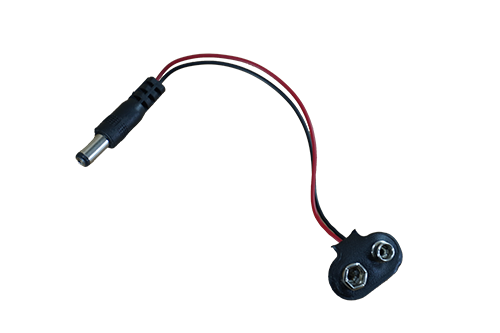 |
| 1 x battery | 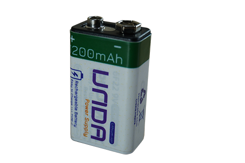 |
| 1 x Unda Xplora | 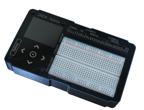 |
Step 1
Connecting the Pushbutton on the breadboard
- Step
- Build
-
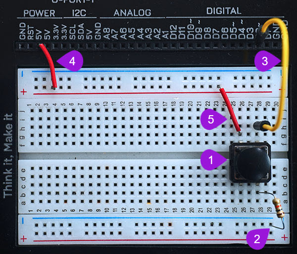
Connecting the pushbutton: Take one pushbutton and connect it's two top pins into pin c28 and pin c26. Insert the two bottom pins into pin f28 and pin f26. It is worth noting that as long as the top pins are inserted correctly, the bottom pins will easily insert into their respective pins.
-
Connecting a 10 Kilo-ohm resistor: Take one 10 Kilo-ohm resistor and connect one of its' end into any pin of the bottom breadboard rail. Insert the other end into breadboard pin b28 next to one of the bottom pins of pushbutton.
-
Connecting the button to digital pin D2: Using a jumper wire(pick any color of your choice), connect from digital pin D2 to one side of the pushbutton at breadboard pin h28 of the breadoard.
-
Connecting power to the breadboard: Using a breadboarding jumper wire, connect from any 5V pin of the UNDA.Xplora to any breadboard pin of the top positive breadboard rail as shown above. Remember that the positive rail is marked with plus (+) sign and marked by red solid line.
-
Connecting the button to power: Take a second breadboarding jumper wire and insert one of the ends of the breadboarding wire into any breadboard pin of the top positive breadboard rail. Insert the second end of the breadboarding wire into breadboard pin g28 next to the second top pin of the pushbutton.
Step 2
Connecting the LED on the breadboard
- Step
- Build
-
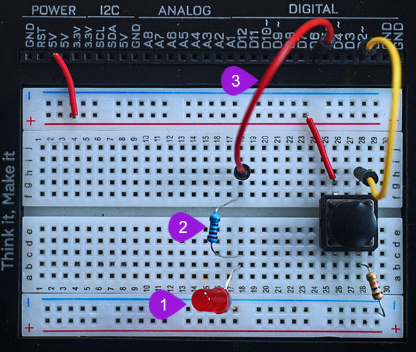
Placing the LED: Take a Red LED from your Unda Xplora Kit. Identify the positive and negative pin of the LED. The positive pin has a longer leg than the negative pin. Insert the LED on the breadboard with the negative leg of the LED placed on the negative bottom breadboard rail and the positive leg placed on the breadboard at pin b18.
-
Inserting the resistor: Pick a 220-ohm resistor and plug one of the resistor's end into breadboard pin c18 next to the positive led og the LED. Plug the other end of the resistor into breadboard pin f18.
-
Connecting a jumper wire: Take a jumper wire and plug one of it's leg into digital pin D6 and insert the other leg into breadboard pin h18 next to the resistor.
Step 3
Connecting the Buzzer on the breadboard
- Step
- Build
-
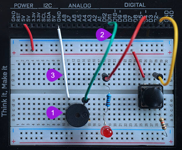
Placing the buzzer on the breadboard: Take the buzzer from the kit. Take note of the positive and negative leg: The positive leg is longer leg and it has been been labelled with a plus sign (+). The negative pin of the buzzer is the leg with the shortest length. Insert the positive leg of the buzzer into pin b14 of the breadboard and insert the negative leg of the buzzer into pin b11 of the breadboard.
-
Connecting a jumper wire to digital pin 12: Pick a jumper wire of any color of your choice and connect it from digital pin D12 of the kit to one side of the buzzer at breadboard pin e14 of the breadboard.
-
Connecting to the negative pin of the buzzer: Using a breadboaridng jumper wire, connect from top negative breadboard rail to the breadboard pin e11 which is next to the negative pin of the buzzer.
Step 4
Connecting the Light Sensor on the breadboard
- Step
- Build
-
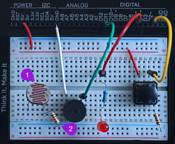
Inserting the Light Sensor: Pick the Light Sensor from the Tinker components casing. The light sensor has two legs and it also has no polarity and thus you can connect it in any orientation. Insert the one of its' legs into breadboard pin b6 and then plug the other leg of the light sensor into breadboard pin b3.
-
Connecting the sensor to a resistor: Pick a 10K (10 Kilo-ohm) resistor from the components casing. Insert one of the ends of the resistor into any pin on the bottom negative breadboard rail. Plug the other end into breadoard pin a6 next to one of the legs of the light sensor.
Step 5
Wiring the Light Sensor
- Step
- Build
-
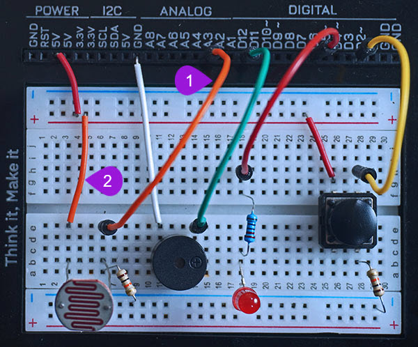
Connecting the Light sensor to analog pin: Pick a jumper wire of any colour of your choice and plug one of its' end into analog pin A3 of your UNDA.Xplora. Plug the other end of the jumper wire into breadboard pin e6 next to the second pin of the light sensor.
-
Connecting the Light sensor to power: Connect the sensor to power by inserting another jumper wire from any 5V pin of your kit to breadboard pin e3 next to the first pin of the light sensor.
Step 6
Connecting the circuit to Ground
- Step
- Build
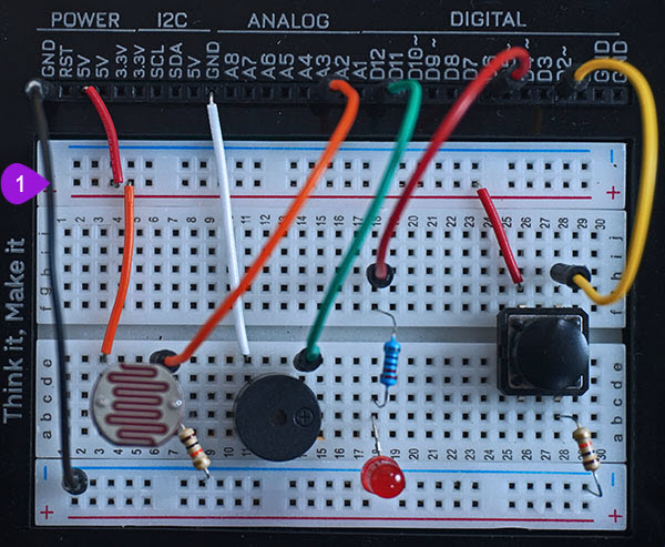
- Connecting to Ground(GND): Take another jumper wire from the Tinker Components casing. Plug one end of the jumper wire into any GND pin of the kit and then proceed to plug the other end of the jumper wire into any pin of the bottom negative breadboard rail.
Run the Project
Once you are done with building the project, connect the battery to the the battery connector and then plug it to the power port of your Unda Xplora to power it on.
Follow the steps below to load up the Safe Box Project.
Open Project
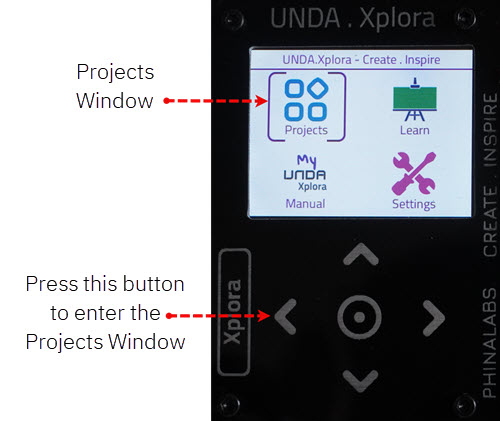
From the main window open the projects